Automotive Cable Assembly: Design and Testing Explained

You depend on automotive cable assembly design and testing to keep your vehicle safe and running smoothly. Reliable cable assemblies protect critical systems like airbags and brakes from electrical failures. Advanced materials and smart construction help these assemblies resist heat, moisture, and wear.
High-quality automotive cable assembly supports fast data and power flow for modern features.
Careful testing and regular inspection prevent problems that could put safety at risk.
Lightweight designs also help your car use less fuel and perform better.
Key Takeaways
Automotive cable assemblies connect important vehicle systems and must be designed with the right materials and construction to handle heat, moisture, and movement.
Testing cable assemblies through visual, electrical, mechanical, and signal integrity checks helps find problems early and ensures safety and reliability.
Using clear drawings and following industry standards improves manufacturing accuracy and helps build durable, high-quality cable assemblies.
Automated testing systems speed up inspections, reduce errors, and provide detailed data to improve production and quality control.
Strong design, careful material choice, and thorough testing keep automotive cable assemblies working well, supporting vehicle safety and advanced features.
Automotive Cable Assembly Basics

What Is an Automotive Cable Assembly
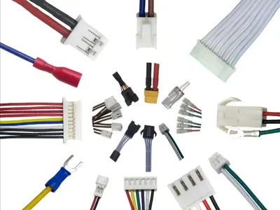
You find automotive cable assemblies in every modern vehicle. These assemblies help your car send power and signals to important systems. Each automotive cable assembly includes several main parts. You see conductors, usually made from copper, that carry electricity or data. Insulators made from strong polymers protect these wires from outside interference. Connectors join different parts of the assembly, making sure signals flow smoothly. You also notice protective sleeving, cable ties, and clamps. These keep the assembly organized and safe from damage. Some assemblies use ferrules, which are small metal tubes, to keep wire strands together and prevent fraying.
Note: Industry standards like IPC/WHMA-A-620 and SAE set strict rules for the quality and safety of every cable assembly. These standards help you trust that each assembly will work well in your vehicle.
Role in Automotive Wire Harnesses
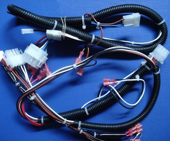
Automotive cable assemblies play a key role in automotive wire harnesses. You can think of a wire harness assembly as a bundle that brings together many cable assemblies into one neat unit. This makes installation easier and keeps your car’s wiring organized.
Wire harnesses combine cables, wires, and connectors to fit your vehicle’s shape and needs.
This integration helps your car handle high currents and resist heat or vibration.
You get better reliability and less risk of electrical problems.
Here is a quick comparison to help you understand:
Aspect | Description |
|---|---|
Automotive Cable Assemblies | Bundles of wires and connectors designed to transmit power, signals, and data within vehicles. |
Wire Harnesses | Structured bundles of multiple cables and wires organized into a single unit for installation. |
Integration | Harness cable assemblies group multiple cable assemblies into one harness for space-saving and ease of installation. |
Function | Both ensure reliable electrical connectivity, support safety systems, and enable advanced vehicle features. |
Outcome | Integration results in complex, durable, and efficient electrical networks tailored to vehicle needs. |
When you look at your vehicle’s wiring harness, you see how cable assemblies work together to keep everything running safely and smoothly.
Design of Cable Assemblies
Design Considerations
When you start designing automotive cable assemblies, you need to focus on several important factors. Each decision you make affects how well the assembly works and how long it lasts in your vehicle. Here are the most critical design considerations you should keep in mind:
Understand the application requirements early. This helps you avoid making the assembly too simple or too complex for its job.
Select the right conductor size. The size must match the electrical load and the temperature where the assembly will work.
Choose the best conductor material. Copper and copper alloys give you a good balance of electrical performance and strength.
Think about how the conductor is built. Stranded conductors, such as bunched lay or rope lay, offer more flexibility and better endurance than solid wires.
Use plating like tin, silver, or nickel. Plating protects against corrosion and makes soldering easier, especially in wet or hot places.
Pick insulation materials that match the environment. Rubbers and thermoplastics can handle different temperatures and chemicals.
Add shielding if you need to block electromagnetic interference. You can use braid, spiral, or foil shields to keep signals clear.
Make sure you connect the shield to the connectors at both ends. This keeps the shield working well. 9. Use fillers and tapes to improve the shape, strength, and noise resistance of the assembly.
You also need to think about custom cable assemblies. These let you match the design to special needs, such as tight spaces or extra flexibility. If you want your assembly to last, you must consider flex life. Flex life means how many times the cable can bend before it breaks. Good design choices help your cable assemblies survive the constant movement and vibration inside a car.
Tip: Always check the environment where the assembly will be used. Heat, moisture, and chemicals can shorten the endurance of your cable assemblies if you do not choose the right materials.
Cable Assembly Drawings
You need clear and detailed drawings to build cable assemblies that work every time. A professional cable assembly drawing gives you all the information you need for accurate and repeatable manufacturing. Here is what you will find in a typical drawing:
Physical layout and dimensions, including the total length, branch sizes, and where each connector goes.
Pinouts and wiring details, showing which wire connects to which pin, the wire gauge, and how the wires are insulated or shielded.
A bill of materials (BOM) that lists every part, from wires and connectors to labels and sleeves.
Step-by-step assembly instructions, including which tools to use and where to check for quality.
Cable routing paths, showing how the assembly should be installed in the vehicle, including bend radii and mounting points.
Cable management details, such as where to place cable ties, sleeves, and protective covers.
Safety notes and warning symbols to help you avoid mistakes and follow industry standards.
Digital files, like CAD drawings and PDFs, help you share and update designs quickly.
The table below shows how each part of a drawing helps you get consistent results in manufacturing:
Drawing Element | How It Helps Manufacturing Accuracy and Consistency |
|---|---|
Title Block | Gives you clear information about the drawing, such as part number and revision, so you always use the right version. |
Scale | Shows the correct size, so you avoid mistakes in length or spacing. |
Drawing Views | Lets you see the assembly from different angles, making it easier to understand and build. |
Symbol Library | Uses standard symbols, so everyone on your team understands the same thing. |
Wiring Diagrams | Shows you exactly how to connect wires, reducing wiring errors. |
Wire Routing | Guides you on how to bundle and secure wires, protecting them from damage. |
Connector Information | Helps you match connectors and wires correctly, avoiding mix-ups. |
Wire Identification | Uses labels and colors to make troubleshooting and assembly faster. |
Bill of Materials | Lists all parts, so you do not miss anything during assembly. |
Revision Control | Tracks changes, so you always have the latest and most accurate design. |
You can use digital databases to store and manage these drawings. This lets you pull up the latest design fast and reduces mistakes from manual data entry. Automated systems also track quality checks and help you spot problems early, which improves the endurance and reliability of your cable assemblies.
Materials and Construction
The materials you choose for your cable assemblies decide how well they perform and how long they last. You need to pick materials that match the job and the environment. Here is a table showing common materials and their advantages:
Material Type | Material | Advantages |
|---|---|---|
Conductive Materials | Copper | High electrical conductivity, flexible, resists corrosion |
Aluminum | Good conductivity, lightweight, helps reduce vehicle weight | |
Nickel-Chromium | Handles high temperatures, resists oxidation and corrosion | |
Copper-Nickel | Good conductivity, excellent corrosion resistance, works well in harsh environments | |
Insulation Materials | Teflon (PTFE) | Handles high heat, resists chemicals, low friction |
Silicone | Flexible, resists high temperatures, common in automotive insulation | |
Polyimide (Kapton) | Stable at high temperatures, great electrical insulation | |
Shielding Materials | Copper Braiding | Strong EMI protection, flexible, durable |
Aluminum Foil | Lightweight, good EMI shielding | |
Additional Examples | XLPE | Protects against heat and shock, used in heavy-duty cables |
Tinned Copper | Resists corrosion, used in conductors |
When you build custom cable assemblies, you can select special materials to meet unique needs. For example, you might use polyurethane for its flexibility and abrasion resistance, or thermoplastic elastomers for chemical and oil resistance. Overmolding with materials like Santoprene or PVC gives you extra protection against moisture and wear. This helps your cable assemblies survive tough conditions and keeps them working longer.
Material selection also affects the flex life and environmental resistance of your assembly. Silicone and cross-linked polyethylene handle high temperatures, while thermoplastic elastomers stay flexible in the cold. If you need your cable assemblies to last through many bends and twists, you must choose materials that support high endurance. Advanced materials like engineered fluoropolymers can handle extreme temperatures and chemicals, making them ideal for harsh automotive environments.
Note: If you pick the wrong material, your cable assemblies may fail early, especially in wet or hot places. Always match your material choice to the real-world conditions your assembly will face.
Cable Harness Testing Methods

Automotive cable harness testing helps you find problems before they cause failures in your vehicle. You use different tests to check the safety, durability, and performance of each electrical cable harness. These methods help you make sure every cable assembly meets strict industry standards.
Visual Inspection
You always start cable harness testing with a careful visual inspection. This step lets you spot obvious problems before you move on to more advanced tests. You look for damage, poor workmanship, and missing parts. You also check if the cables are routed correctly and if connectors are seated properly. High-resolution images help you find small gaps or misalignments that are hard to see with the naked eye.
Here is a table that shows the main steps and tools you use during visual inspection:
Inspection Aspect | Procedure / Criteria | Tools / Methods Used | Quantifiable Metrics / Standards |
|---|---|---|---|
Checklist Design | Itemized checks by harness ID (e.g., insulation, terminal oxidation) | Checklist with embedded metrics | Mating force: 20-50N; example pass: 38N |
Photo Documentation | Capture overview and close-up images of anomalies | Naming convention: DeviceID_HarnessID_Date | – |
Assistive Technologies | AI image analysis for aging detection (92% accuracy), RFID tracking for inspection history | AI models, RFID scanners | – |
Insulation Integrity | Visual check for cuts/cracks, magnifiers/endoscopes for hidden areas | Magnifiers, endoscopes | Wear <10% thickness reduction: monitor; cracks >0.5mm: replace |
Aging and Deformation | Tactile hardness evaluation, thermal imaging for overheating signs | Thermal imager | Replace if yellow discoloration or bulging detected |
Environmental Damage | Check for chemical corrosion (pH test strips), biological damage (rodent marks) | pH test strips, visual inspection | – |
Connector and Terminal | Clean oxidation with ethanol, check deformation, insertion/extraction force testing | Ethanol swabs, force testers, OEM drawings | Replace gold-plated terminals with >30% oxidation |
Mating Performance | Measure insertion/extraction forces, verify locking clicks | Digital torque gauges | Typical force: 20-50N; replacement after rated cycles |
Sealing Verification | Air-tightness tests for waterproof connectors, inspect rubber gaskets | Pressure tests (0.5Bar), visual inspection | Leakage <5% in 30s for IP67+ connectors |
Mechanical Structure | Check cable ties/clips for breakage/looseness, maintain clearance from moving parts | Visual inspection | ≤2mm displacement allowed; ≥50mm clearance recommended |
Environmental Adaptability | High-temp oven test (125°C/24h), low-temp flexibility test (-40°C), simulated rain and dust tests | Oven, bending tests, humidity sensors | Insulation crack inspection post-test; humidity ≤85%RH |
Inspection Cycles | Routine every 10,000 km or 6 months; after extreme conditions; NEV high-voltage wiring insulation tests | Scheduled maintenance, condition-based inspections | Insulation resistance tests every 3 months for NEV wiring |
During visual inspection, you often find these common defects:
Improper cable routing that can lead to pinching or damage
Misaligned or loose connectors, which may cause poor electrical connections
Missing screws, making parts loose or unsafe
Subtle defects like small connector gaps or slight misrouting
Wire deformities, such as bends or damage
Incorrect crimp placement or loose crimps
Birdcaging, where wires splay out instead of staying bundled
Insulation defects like cracks, fraying, or discoloration
Contact points with visible defects
You also check that insulation covers the wire beyond the crimp tab and that all enclosures are secure. This step in cable harness testing helps you catch problems early and avoid costly repairs later.
Electrical Testing
After visual inspection, you move to electrical cable harness testing. These tests help you make sure the harness works safely and reliably. You use several types of electrical tests to check for breaks, shorts, and insulation problems.
Here is a table showing the main electrical tests and their purposes:
Test Type | Purpose |
|---|---|
Verifies uninterrupted electrical flow through wires, ensuring secure connections. | |
Insulation Resistance Test | Measures insulation quality by applying high voltage and checking resistance to leakage. |
High Voltage (Dielectric) | Tests harness ability to withstand voltages above normal operating levels without failure. |
Functional Testing | Simulates actual operation to confirm overall harness performance and component integration. |
Contact Resistance Test | Measures resistance at connectors to ensure good conductivity and detect poor crimps. |
Short Circuit Test | Detects accidental wire contacts that could cause shorts, verifying proper assembly. |
You use continuity testing to check that every wire in the harness has a complete path. This test sends a small electrical signal through each wire. If the signal does not reach the end, you know there is a break. You repeat continuity testing for every wire to make sure the electrical cable harness has no interruptions.
Insulation resistance tests help you find leaks between wires and insulation. You apply a high voltage and measure how much current leaks through the insulation. Good insulation keeps the current low. If you find high leakage, you replace the harness.
High-voltage (hipot) tests push the harness to handle voltages higher than normal. This test helps you find weak spots in the insulation that could fail under stress. Contact resistance tests check the quality of crimps and connectors. Low resistance means a good connection. High resistance means you need to fix or replace the part.
You also run functional tests to simulate real-world use. You check if the harness can transmit power and data as needed. These tests help you confirm that the electrical cable harness will work in your vehicle.
Other important electrical cable harness tests include:
Flame resistance tests to check fire safety
EMC and shielding tests to prevent electromagnetic interference
You use these tests to make sure your cable harness testing covers every possible risk.
Mechanical and Environmental Testing
You need to know that your cable harness can survive tough conditions. Mechanical and environmental tests help you check the strength and durability of each electrical cable harness. These tests show how the harness will perform in real-world automotive environments.
Here is a table of common mechanical and environmental tests:
Test Category | Test Name / Type | Purpose / Description |
|---|---|---|
Mechanical Tests | Pull Tests (pull and break, pull, hold and break, pull and hold, pull and release) | Evaluate cable strength and connector durability under tensile forces. |
Flex/Bend Test | Assess cable performance under bending, twisting, and flexing to ensure signal integrity during movement. | |
Verify cable’s ability to withstand mechanical shocks without damage. | ||
Insulation Concentricity and Wall Thickness | Measure insulation uniformity and thickness to ensure quality and durability. | |
Environmental Tests | Thermal Shock | Test cable resilience to rapid temperature changes. |
Waterproofness (IP66/IP67) | Confirm protection against dust and water ingress under specified conditions. | |
Humidity | Assess cable performance under high moisture conditions. | |
Vibration | Evaluate cable durability under mechanical vibrations. | |
High/Low Temperature Storage | Test cable stability and performance after exposure to extreme temperatures. | |
Fungus Exposure (Fungal Resilience Test) | Ensure resistance to fungal growth in warm, humid, or marine environments. | |
Salt Spray | Assess corrosion resistance due to salt exposure. | |
Chemical and Fluids Exposure | Test cable resistance to various chemicals and fluids. | |
Immersion Leak Detection | Verify seal integrity and airtightness to prevent fluid leakage. |
You use pull tests to check how much force the harness can handle before breaking. Flex and bend tests, like the Tick-Tock Tester, simulate the bending and twisting that cables face in a moving car. These tests help you see if the harness can keep its signal integrity during constant movement.
Heat resistance tests use temperature chambers to expose the harness to extreme heat and cold. You want to know if the insulation cracks or if the cable loses strength. Vibration and impact resistance tests show if the harness can survive bumps and shocks on the road.
You also test for waterproofness by submerging the harness and checking for leaks. Salt spray and chemical exposure tests help you see if the harness can resist corrosion. These mechanical and environmental tests make sure your cable harness testing covers every challenge your vehicle might face.
Signal Integrity Testing
Modern vehicles use advanced electronics that need clean, reliable signals. Signal integrity testing helps you make sure your electrical cable harness can transmit data without distortion or loss. You use several tests to check for problems like interference, signal loss, and timing errors.
Key signal integrity tests include:
Impedance testing, which checks if the cable impedance matches the required value. This test is critical for high-frequency signals.
EMI and EMC testing, which help you find and fix electromagnetic interference problems.
Insertion loss and return loss measurements, which show how much signal is lost or reflected.
Crosstalk tests, which check if signals from one wire interfere with another.
Propagation delay and time skew tests, which measure how fast signals travel and if they stay in sync.
Here is a table showing important figures of merit for signal integrity tests:
Figure of Merit | Description | Importance |
|---|---|---|
Insertion Loss | Attenuation of signal from input to output, measured in dB | Indicates signal attenuation; ideal is 0 dB |
Return Loss | Loss due to signal reflections from impedance mismatches, in dB | Measures signal reflection, affecting integrity |
Crosstalk | Unwanted signal coupling from adjacent wiring, in dB | Indicates interference between lines |
Propagation Delay | Time taken for signal to travel through the cable | Affects timing and synchronization |
Time Skew | Time difference between signals on multiple lines | Critical for multi-lane data transmission synchronization |
You use oscilloscopes, vector network analyzers, and other advanced tools to run these tests. These tools help you find problems with timing, jitter, and noise. You also use signal integrity tests to check if your cable harness can support high data rates and low voltages, which are common in new vehicles.
Advanced cable assemblies, like Eye Speed micro coax and twinax cables, show low insertion loss and minimal timing skew. These features help you maintain signal integrity even at high speeds. Good signal integrity testing helps you avoid data errors and keeps your vehicle’s electronics running smoothly.
Tip: Always include signal integrity tests in your cable harness testing plan. These tests help you catch problems that can affect advanced automotive electronics, such as timing errors and data loss.
By following these cable harness testing methods, you make sure your electrical cable harness meets all safety, durability, and performance standards. You protect your vehicle from failures and keep every system running as it should.
Automation in Testing
Automated Test Systems
You can make your cable harness testing faster and more reliable by using an automated electrical cable harness testing system. These systems use advanced tools and software to check every wire and connection in your harness. Here are some common parts you will find in an automated electrical cable harness testing system:
Hipot testers check insulation resistance and high-voltage safety.
Multi-point switching systems handle many test points at once, making it easy to test complex harnesses.
Automation software controls the whole process, runs test sequences, logs data, and finds faults quickly.
With an automated electrical cable harness testing system, you can run tests like continuity, insulation resistance, and ground bond checks. The system uses relay matrices and software to apply voltage, measure current, and spot problems much faster than manual testing. You can also use scripting to automate workflows and connect the testing system to other machines in your factory. This approach helps you test every wire, even in large and complex harnesses, with high testing accuracy.
Tip: Automated cable testing can reduce test times from hours to just minutes, even for harnesses with hundreds of connections.
Benefits of Automation
When you use an automated electrical cable harness testing system, you get many benefits that improve your production process. Here is a table showing how automation helps you:
Benefit | How It Helps You |
|---|---|
Improved Quality & Accuracy | Reduces human error and ensures repeatable, precise testing results. |
Increased Efficiency | Runs complex test sequences quickly, saving you time and boosting productivity. |
Data Management & Traceability | Records all test data for quality checks and future tracking. |
Safety | Keeps workers safe by enclosing high-voltage tests and reducing manual handling. |
Adaptability | Handles complex harness designs for electric and advanced vehicles. |
Cost Reduction | Cuts labor costs and waste, making your production more competitive. |
You can also track every step of the process with automated systems. Manufacturing Execution Systems (MES) assign unique codes to each harness, record test results, and link them to specific machines and workers. This traceability helps you find and fix problems fast, manage recalls, and meet industry standards. Automation also helps you keep up with changing customer needs and supports just-in-time production.
By using an automated electrical cable harness testing system, you make your cable harness testing more accurate, faster, and safer. You also collect valuable data that helps you improve quality and stay ahead in the automotive industry.
Applications and Compliance
Real-World Applications
You see automotive cable assemblies everywhere in modern vehicles. These assemblies help your car send power and signals to important systems like lights, engines, radios, and sensors. They keep your vehicle running safely and smoothly, even when facing heat, cold, moisture, or chemicals. Different types of cables, such as XLPE-insulated and PVC-insulated wires, match the needs of each system. For example, battery cables handle high power, while shielded cables protect sensitive electronics from interference.
Here are some key ways cable assemblies work in your vehicle:
Electrification increases wiring complexity and weight, especially in electric cars.
Autonomous driving needs extra wiring and backup systems for safety and reliability.
Artificial intelligence adds more sensors and control units, all connected by complex harnesses.
Connected vehicles use special cables for infotainment and communication networks.
You might find up to 40 harnesses, 700 connectors, and 3,000 wires in a single car. Each assembly supports a different function, from engine control to door locks. The table below shows how different harnesses serve your vehicle:
Type of Wire Harness | Application in Vehicle |
|---|---|
Engine Wire Harness | Connects battery, alternator, sensors; handles heat and vibration. |
Chassis Wire Harness | Powers lights, ABS sensors, suspension modules. |
Body Wire Harness | Runs sound systems, interior lights, and safety features. |
Door Wire Harness | Controls power windows, locks, and mirrors; built for flexibility. |
Dashboard Wire Harness | Powers speedometer, warning lights, GPS, and entertainment. |
Powertrain Wire Harness | Links transmission, engine, starter, and alternator for smooth operation. |
You also rely on cable assemblies for advanced driver-assistance systems (ADAS) and infotainment. Ethernet, CAN, and fiber optic cables help transfer data quickly between sensors, cameras, and control units. These connections keep your vehicle safe and connected.
Standards and Quality
You need strong standards and quality assurance to keep automotive cable assemblies reliable. International standards guide every step of design and manufacturing. The ISO 19642 series covers vocabulary, design rules, and test methods for many types of cables. ISO 6722 and ISO 4141 focus on single-core and multi-core cables. ISO 6856 sets rules for ignition cable assemblies. ISO 19453 covers environmental testing for electric vehicles. These standards help you trust that each assembly meets strict requirements for safety and performance.
Standard Series / Number | Title / Scope | Focus Area |
|---|---|---|
ISO 19642 series | Automotive cables—design guidelines, test methods, requirements for copper and aluminum cables | Design and testing of automotive cables |
ISO 6722 series | Single-core cables—dimensions, test methods, requirements | Single-core cable design/testing |
ISO 4141 series | Multi-core connecting cables—test methods, requirements, construction | Multi-core cable design/testing |
ISO 6856 | Unscreened high-voltage ignition cable assemblies—test methods, requirements | Ignition cable assemblies |
ISO 19453 series | Environmental conditions and testing for electric vehicles | Environmental testing |
You also see quality management systems like ISO 9001 and IATF 16949 in action. These systems help suppliers set goals, improve processes, and meet customer needs. IATF 16949 builds on ISO 9001 and focuses on continual improvement, defect prevention, and reducing waste. Tier 1 suppliers must have IATF 16949 certification, while others start with ISO 9001. These standards require you to use tools like APQP, FMEA, and PPAP for quality assurance. They help you deliver consistent, high-quality assemblies that keep vehicles safe and reliable.
Tip: Following these standards and quality systems helps you avoid costly recalls and ensures your assemblies meet the highest safety and performance levels.
You gain lasting value when you focus on strong design and testing for automotive cable assemblies. These steps help you meet strict standards, improve reliability, and reduce failures.
Use advanced testing, like burn-in and vibration checks, to find weaknesses early.
Choose materials and designs that match your needs and environment.
Industry leaders use dedicated QA rooms, lean manufacturing, and modular design to keep quality high. When you follow these best practices, you build assemblies that last and perform well in every vehicle.
FAQ
What is the difference between a cable assembly and a wire harness?
A cable assembly groups wires together with connectors and protective covers. A wire harness organizes many cable assemblies into one bundle. You use cable assemblies for specific tasks. You use wire harnesses to connect many systems in your vehicle.
How often should you test automotive cable assemblies?
You should test cable assemblies during production and before installation. You also need to check them during regular vehicle maintenance. Testing helps you find problems early and keeps your vehicle safe.
Why do you need shielding in automotive cables?
Shielding blocks electromagnetic interference (EMI). You use shielding to protect signals from outside noise. This keeps your car’s electronics working without errors or data loss.
What tools help you test cable assemblies?
You use tools like multimeters, hipot testers, and automated test systems. These tools check for breaks, shorts, and insulation problems. Automated systems also record test results for quality control.
Can you repair a damaged cable assembly, or should you replace it?
You can repair minor damage, like a loose connector or small insulation nick. For major damage, such as broken wires or burned insulation, you should replace the assembly. This keeps your vehicle safe and reliable.