
Automotive Body Wiring Harness: Projeto, Build and Quality Checks That Prevent Field Failures
Automotive Body Wiring Harness: Projeto, Build and Quality Checks That Prevent Field Failures
An automotive body wiring harness is the nervous system that carries power and signals between the body modules, portas, seats, lighting and the instrument panel. When it fails, the symptoms look like component failures, and the diagnosis usually lands on the wrong part. This guide covers how a body harness is designed and built, what quality controls separate a reliable harness from a warranty claim, and what to verify with your supplier before production.
What an Automotive Body Wiring Harness Actually Does
The body harness routes every electrical function in the vehicle body: interior lighting, window regulators, door locks, seat adjustment, airbag circuits, wipers, audio and the connections to the body control module. It is typically the largest harness in the vehicle by wire count, and it must survive the full life of the car, including temperature cycling, vibração, moisture and repeated door operation.
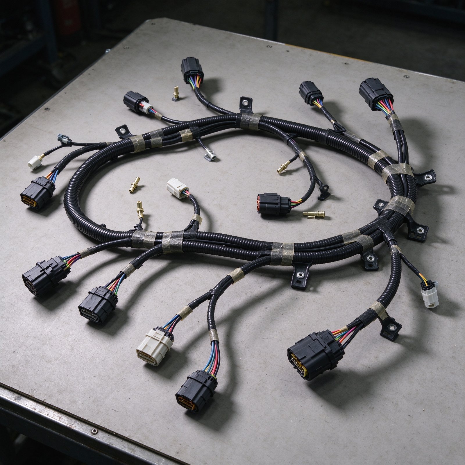
Because the body harness touches so many functions, its design has to balance electrical performance, routing constraints, weight and cost. Every branch is sized for its current, every connector is chosen for its environment, and every segment is routed to avoid chafing, heat sources and moving parts.
Getting these decisions wrong at design stage turns into intermittent faults that are almost impossible to trace after assembly. The connection-level principles are covered in our automotive harness connector sealing guide.
Wire Sizing and Circuit Protection: Getting the Basics Right
Every circuit in the body harness starts with wire sizing. The conductor must carry the maximum expected current with a safety margin, or it overheats, degrades its insulation and eventually fails. Automotive wire specifications such as SAE J1128 define current ratings for wire gauges at defined ambient temperatures, and the fuse rating has to protect the smallest wire in the circuit, not the largest.
In practice, this means the harness designer works backwards from the load: nominal current, inrush current, ambient temperature at the routing location and the voltage drop the module can tolerate. Undersized wire is the classic root cause of melted insulation and intermittent opens; oversized wire wastes weight and cost across thousands of vehicles.
Connector Selection and Terminal Design
A body harness fails more often at connectors and terminals than in the wire itself. The connector must match the environmental exposure: sealed connectors for door and body areas that see water, unsealed for dry interior cavities, and the terminal design must suit the wire gauge and the expected insertion and extraction cycles.
Terminal crimp quality is where manufacturing discipline shows. Under IPC/WHMA-A-620, crimping is the required termination method for automotive circuits, and each crimp has to meet defined height, width, insulation grip and conductor exposure criteria.
A harness built with consistent, documented crimp quality will pass electrical test consistently; one built with operator-dependent crimping produces intermittent failures that pass final test and fail in the field. The full process discipline is explained in our guia de processo de crimpagem de chicote de fios.
Roteamento, Protection and Environmental Design
The physical routing of the body harness decides its long-term survival. Wires that pass through door hinges need flexible, fatigue-resistant construction and enough service loop. Wires near the engine bay need high-temperature insulation. Wires on the floor pan need abrasion protection where they cross edges, and all branches need strain relief at connectors.
Environmental exposure varies across the body: the door cavity sees moisture and temperature swings, the floor sees dirt and mechanical abuse, the roof line sees heat. A properly designed harness specifies the right wire insulation class, manga, grommets and sealing for each zone, rather than using one construction everywhere.
Water and Sealing Strategy
Water ingress is one of the most common causes of body harness corrosion and intermittent faults. The strategy has to cover connectors, splices and harness entry points: sealed connectors where water reaches, grommets where the harness passes through panels, and drainage paths that let any ingress escape before it reaches a connector.
The sealing decision is environmental, not universal. An IP67-rated sealed connector is not needed in every cavity, and specifying it everywhere adds cost and reduces serviceability. The engineering question is where water actually reaches, and the harness design should match the seal level to the exposure.
Testing That Catches Faults Before the Vehicle Leaves
A body harness should be electrically tested 100 percent before assembly: continuity on every circuit, resistência de isolamento, and dielectric withstand where the design requires it. Continuity testing catches opens and miswires; insulation testing catches compromised insulation; and the test records should be traceable to the harness, not a box checked on a form.
Beyond electrical test, first article inspection covers mechanical quality: crimp cross-sections, terminal pull-out forces, connector seating and routing accuracy against the formboard. These are the checks that catch process drift before it becomes a batch of defective harnesses.
Design for Assembly and Service
A harness that is difficult to install on the vehicle line is a harness that gets damaged during installation. Branch lengths, connector access, latching direction and service loops all affect how the harness behaves during assembly and later during repair. Designing for assembly reduces installation damage and makes the difference between a harness that survives handling and one that accumulates hidden damage.
Serviceability matters equally for the owner. Connectors that are accessible and terminals that can be serviced reduce repair cost and repair time, which is why connector position and release mechanisms are design decisions, not afterthoughts.
Lista de verificação de auditoria de fornecedor: 6 Documents Before Production
Before you commit a body harness program to a supplier, request these six documents. Each one verifies a specific engineering claim:
- 1. Wire gauge and circuit protection calculation for your harness, with fuse coordination.
- 2. Crimp qualification report including cross-section analysis and pull-out test data.
- 3. Connector sealing plan matching the environmental exposure of each cavity.
- 4. Electrical test specification: continuidade, insulation resistance and withstand criteria.
- 5. First article inspection report with crimp, routing and assembly validation.
- 6. Environmental test evidence: temperatura, vibration and moisture performance.
A supplier who can produce these documents is running an engineered harness program; one who cannot is assembling wires and hoping. Treat the missing documents as the first finding of your own audit.

Perguntas frequentes: Automotive Body Wiring Harness
What is an automotive body wiring harness?
It is the assembly of wires, connectors and terminals that routes power and signals between body modules, portas, seats, iluminação, airbags and the instrument panel, designed to survive the vehicle’s full operating life.
Why do body harness faults appear as intermittent problems?
Intermittent faults usually come from marginal connections: crimps that pass test but degrade under temperature cycling, or connectors with inadequate environmental sealing. They are hard to reproduce and are best prevented by documented crimp and sealing quality.
What wire standard should automotive harnesses follow?
Automotive wire specifications such as SAE J1128 define current ratings for wire gauges and insulation types, and harness acceptance is governed by IPC/WHMA-A-620. Both should be referenced in your specification.
Why is crimping preferred over soldering in automotive harnesses?
Under IPC/WHMA-A-620, crimping is the required termination for automotive conductor-to-terminal connections because it gives repeatable mechanical and electrical performance. Solder joints are prone to fatigue in vibration and are not the accepted primary method for these circuits.
How do I verify a harness supplier’s quality system?
Request the certification evidence (such as IATF 16949), the crimp qualification report, the electrical test specification and first article inspection records, then audit the production line against them. Documents without a line audit are paperwork.
Contate-nos
Planning an automotive body wiring harness program and need the design and quality documentation in place? Send us your circuit list and environment requirements, and our engineering team will confirm the wire sizing, connector plan and test specification with a free sample program.
Refer to the LCSC wire harness manufacturing guide for an independent overview of the six-stage automotive harness process.
